


3D Mesh Generation
3D Mesh Generator TetGen
TetGen: A
Quality Tetrahedral Mesh Generator and a 3D Delaunay Triangulator is
developed by Hang Si at the Weierstrass
Institute for Applied Analysis and Stochastics (WIAS) in Berlin, Germany.
TetGen is used by FEFLOW
7.5
for generating fully unstructured 3D meshes, for creating 3D partially
unstructured meshes on basis of a layered mesh via the  Meshing panel, and for creating
3D meshes with pinched layers. The various options of TetGen available
in the Meshing panel
are described later in this section.
Meshing panel, and for creating
3D meshes with pinched layers. The various options of TetGen available
in the Meshing panel
are described later in this section.
TetGen Mesh Generation Properties
As for 2D meshing, the mesh quality for tetrahedral meshes (or meshes with unstructured parts) is quite important with relation to numerical stability of the model. Compared to a 2D mesh, a purely visual control of quality is much more difficult to do, and in many cases simply impossible. Thus the Auxiliary Parameters related to mesh quality need to be used to check the mesh created: Max. interior angle of quadrangles, Minimum and Maximum dihedral angles and Condition number. The aim is for a low condition number and large minimum / small maximum dihedral angles.
To achieve a good mesh quality, the properties
for mesh generation with TetGen can be used. As each geometry to be meshed
is different, there is no simple cookbook answer on this. However, at
least the following properties from the Meshing panel
might be worth to mention here:
-
The Quality-mesh generation option is used to turn on a large number of constraints on the mesh quality, among them:
-
Delaunay constrained
-
Radius-edge ratio (values below 2.5 are often considered as OK)
-
Minimum and maximum dihedral angle
-
Global tetrahedron volume constraint
-
Local constraints on area, length and volume for the hull and add-in geometries help to achieve the desired local resolution.
-
The Centroidal Voronoi Tessellation (CVT) option allows to add additional add-in points in the volume to be meshed. The spatial distribution of these points is expected to represent an optimal partition of the domain, for the result of a CVT looks at each point as corresponding to the center of mass of a Voronoi cell. The more points are inserted, the finer and more regular the mesh will be.
-
The option Display mesh quality statistics can be turned on to automatically provide descriptive statistical data on mesh quality after the mesh generation, without having to manually check the Auxiliary parameters.
As for 2D meshing, and maybe even more so, 3D mesh generation should be seen as an iterative process. The mesh generation properties are changed in the process, until the resulting mesh fulfils the requirements of the modeling project at hand. Further details about the generator can be found in section TetGen.
3D Mesh Editing
FEFLOW provides the possibility to change the
topology of a 3D mesh with mesh tools such as Convert
Tetrahedra into 4 Hexahedra and Convert
Hexahedra into 6 Pyramids. They are available under the  Meshing menu.
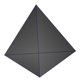
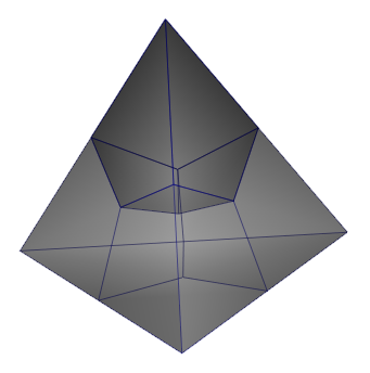
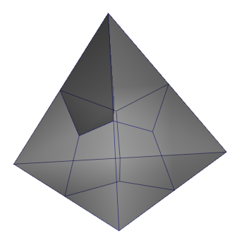
Conversion of one regular tetrahedral (left) to 4 hexahedra (middle) and 24 Pyramids (right). Dark volume in all the cases represents a selected finite-element.
 |
The tool Convert Tetrahedra into 4 Hexahedra is only available for the case of purely tetrahedral meshes and applicable to convert the entire mesh. |
Similar to the 2D mesh operations, the user can improve the mesh quality of a 3D finite-element mesh with options of 3D Mesh Smoothing and 3D Mesh Smoothing - No border node preserved.
|
The 3D Mesh Smoothing - No border node preserved option produces a mesh relaxation (mesh quality improvement) by modifying the node coordinates at any direction. The result of this operation can end up in different model elevations and/or lateral extends of the model domain. |
Modifications of Layered Meshes
Layered meshes can be modified using a number of different operations:
-
Mesh refinement by element subdivision
-
Mesh de-refinement (after previous refinements)
-
Splitting of quadrilateral elements into triangles
-
Smoothing of the mesh at selected node locations or of the entire mesh
-
Flipping element edges
-
Moving nodes within the area of the surrounding elements
Pinching Layers with Tetrahedral Elements
Zones where layers pinch out can be meshed with tetrahedral elements. By using this process, the mesh becomes partly unstructured.
Re-meshing with Tetrahedral Elements
Parts of the model domain can be chosen interactively for re-meshing. Re-meshing is done based on tetrahedral elements, while the connection of the domain parts with a structured (layered) mesh and the new unstructured parts is done by using pyramid elements.
3D Discretization
For 3D models, FEFLOW can apply a layer-based approach, a fully unstructured approach, or a mixture of both.
Layered approach
In case of the layered approach, the triangular, quadrangular or mixed mesh is extended to the third dimension by extruding the 2D mesh, resulting in prismatic 3D elements. In FEFLOW terminology, all (typically) horizontally adjacent 3D elements comprise one layer, while a slice is either the interface between two (typically) vertically adjacent layers or the top or bottom of the model domain. All mesh nodes are located on slices.
The extension of a 2D model to a 3D model is facilitated
by the 3D Layer Configuration dialog
that is accessed via the Edit
menu. Initially defined layers are plane. Real elevations are assigned
like a process variable for each node and can be attributed directly in
the dialog or like any other parameter.
Unless using mixed prismatic/tetrahedral meshing, all the layers in 3D models have to be continuous over the entire model domain. Thus model layers representing lenses or pinching-out stratigraphic layers have to be continued to the model boundary. Typically, they are then assigned a small thickness and the properties of the layer immediately above or below.
The 3D model setup is in most cases based on a vertical extension of a horizontal mesh. For applications such as modeling of dams where a high level of detail is needed vertically, but less along the horizontal axis, the mesh can be generated in vertical projection and extended horizontally. In the latter case, the y axis in FEFLOW points in the direction opposite to gravity, similar to a 2D cross-sectional model.
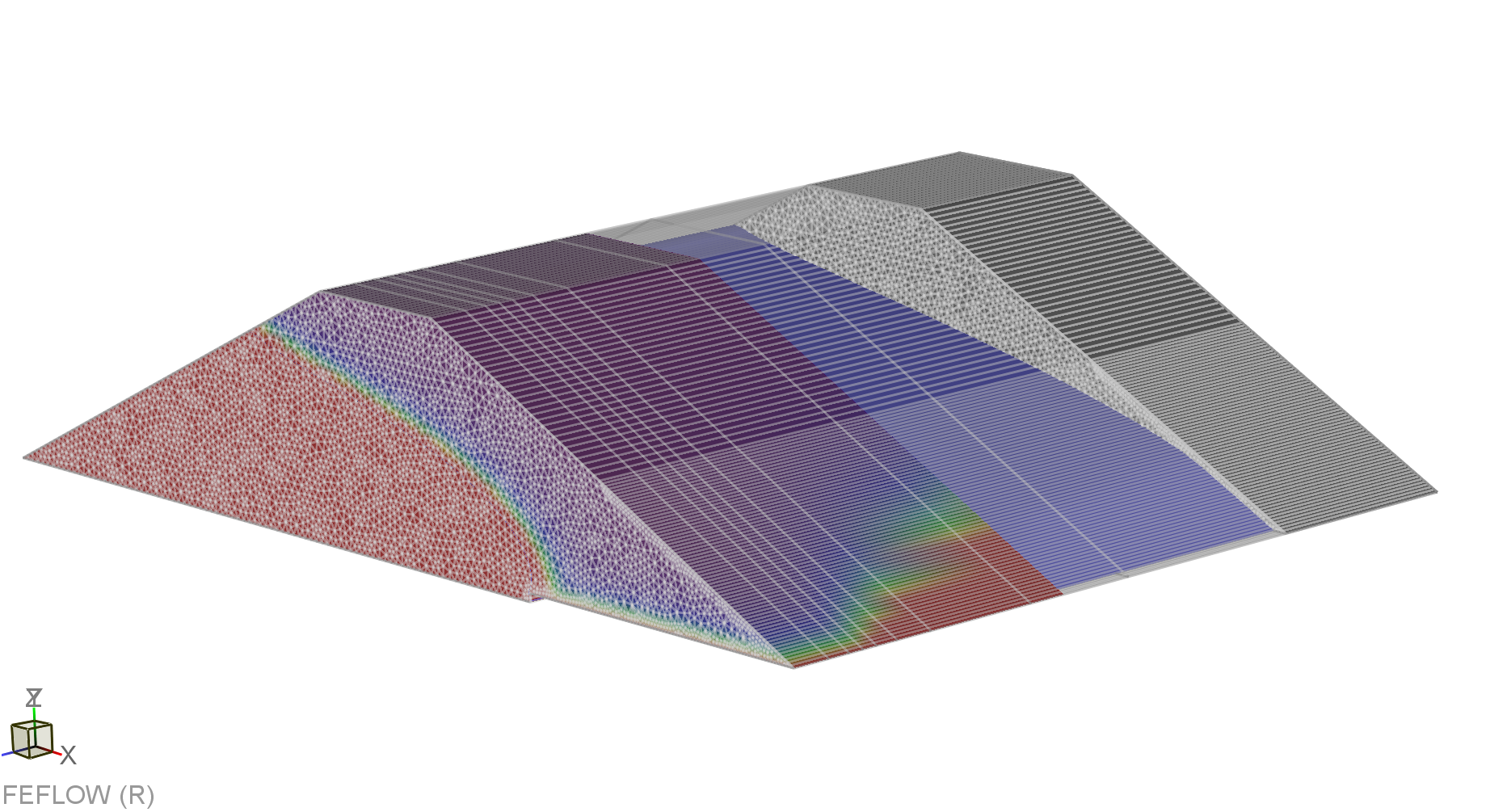
Horizontal and vertical layering approaches.
The 3D Layer Configuration dialog also provides tools to add or remove layers from existing models, and to change layer thicknesses globally.
Partially Unstructured Approaches
Partial Re-Meshing
Setting up a layered model in a fist step, it is possible to re-mesh parts of the model domain with an unstructured mesh in order to refine the mesh or to honour specific geometrical features in the respective part of the model. The chosen part of the domain is re-meshed with tetrahedral elements in this case, and pyramidal elements are used to connect layered and tetrahedral meshes. At re-meshing, the properties of the existing mesh are inherited to the new elements.
Partial re-meshing is done by using the
Meshing panel. The remeshing
volume (or region) is defined by one or a set of elemental selections.
Alternatively, the remeshing process can be constrained by add-ins such
as selection sets (edges, faces or nodes) and 3D map files. In the case
3D maps are used as the so-called Add-ins,
their geometry will be taken into account for the mesh generation process.
Further details of this operation are presented on section Remeshing
Workflow.
 |
The successful use of Add-ins for the generation of unstructured meshes requires that the applied add-ins neither intersect themselves, nor each other or the boundaries of the meshed domain. |
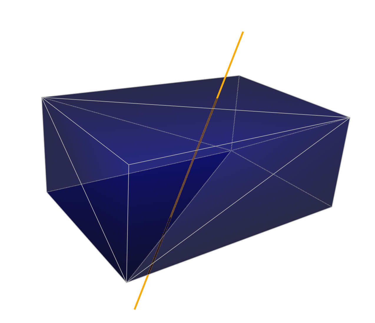
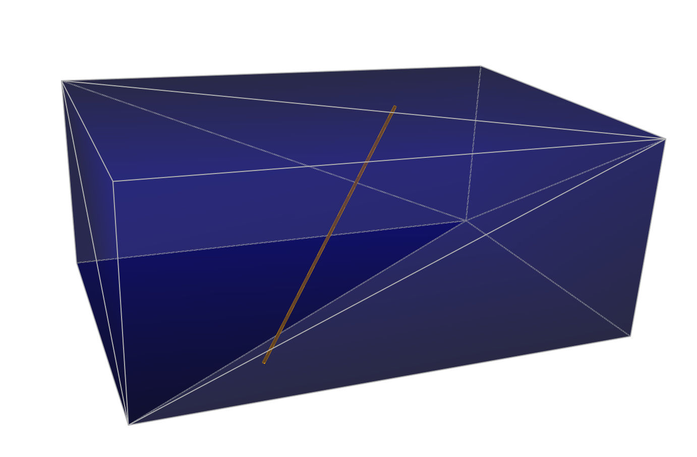
Linear add-in, intersecting the boundary of the domain (left, meshing impossible) and located completely inside the domain (right).
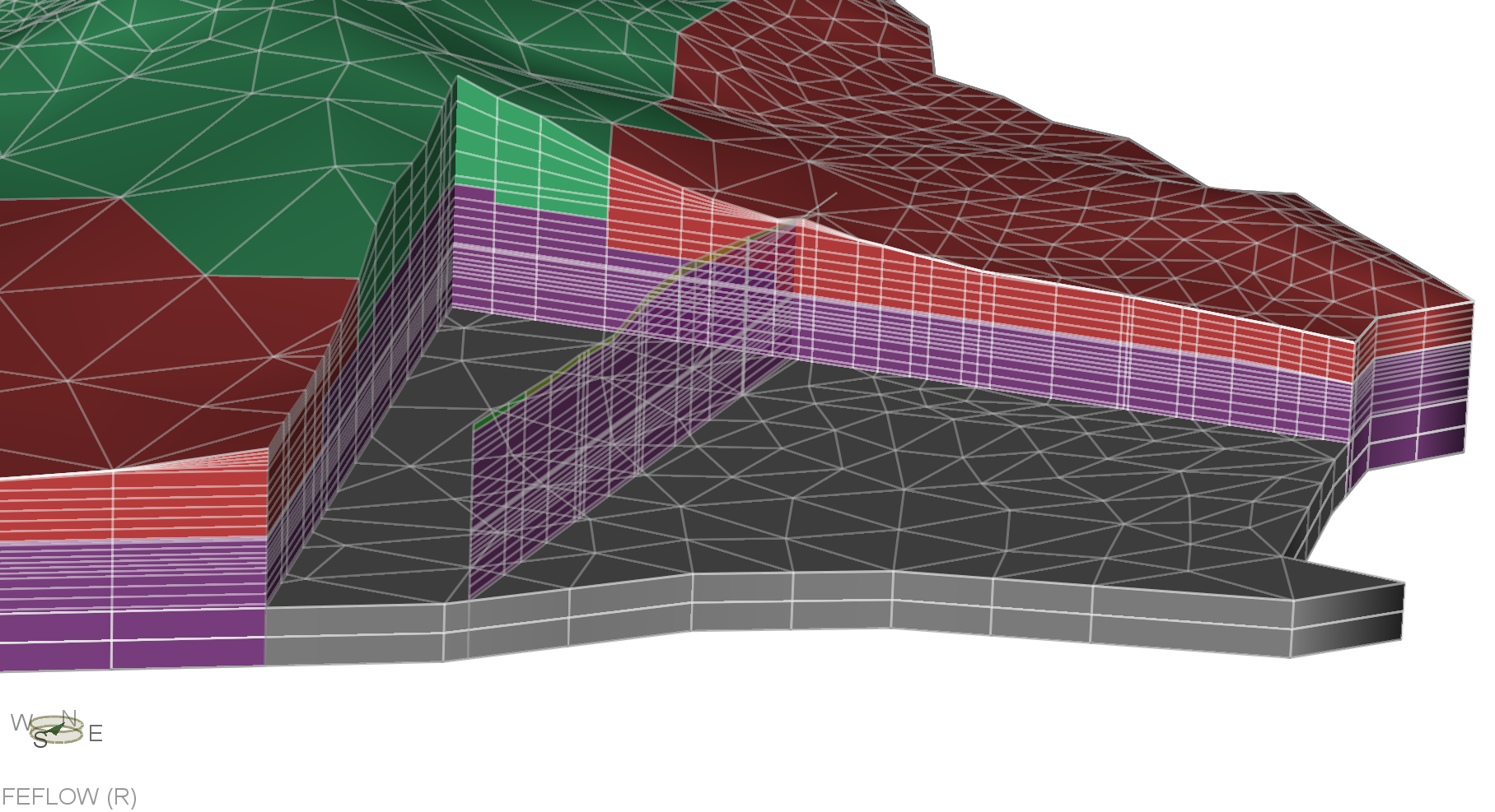
Layer Pinching
Partially unstructured meshing can also be used to implement layer pinch-outs in a layered model. In these cases, a layer pinching out will be meshed with prismatic elements, and only the pinching zone is re-meshed with tetrahedral and pyramidal elements.
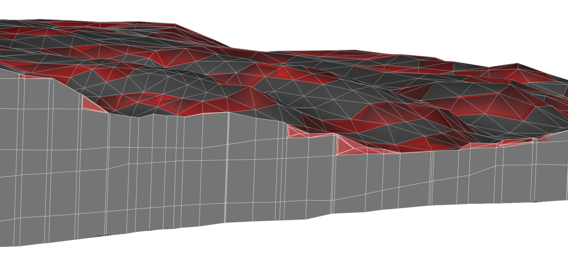
Layer pinching: Cut-out of a model with outcropping layers; tetrahedral/pyramid elements in the outcrop areas are highlighted in red.
Layer pinching is achieved by a specific workflow available in the 3D Layer Configuration dialog. Additional information of this operation is presented in the section Layer Pinching Workflow.
Fully Unstructured Approach
For cases where the geometrical constraints for a model are available in terms of three-dimensional geometries, FEFLOW provides the means to discretize the entire model domain with tetrahedral elements. Major precondition for a successful mesh generation is that the domain and any possible subdomains are defined by closed, non-intersecting and non-self-intersecting surfaces. In typical cases, such geometries are derived from geological modeling software or 3D design software.
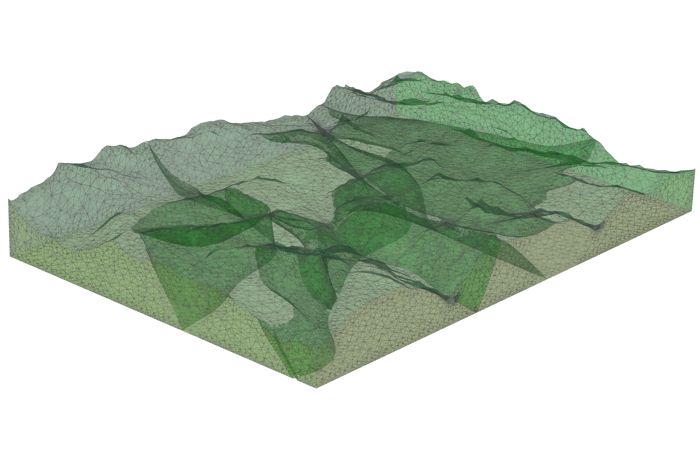
3D Map consisting of triangulated surfaces enclosing a number of subdomains without intersection and self-intersection.
|
The successful generation of an unstructured mesh from 3D map data strictly requires the 3D maps to enclose all subdomains without gaps in the surfaces. No intersections or self-intersections of the surfaces are tolerated. |