


FEFLOW piMIKE1D: User Manual
The former IfmMIKE11 is now officially replaced by FEFLOW piMIKE1D. This new solution offers a native coupling between FEFLOW and MIKE 1D engines for integrated groundwater / surface water modelling. MIKE 1D is the new DHI's generation of surface water engine and is the successor of the former MIKE 11. MIKE 1D engine is part of MIKE Hydro River and MIKE+ products.
FEFLOW piMIKE 1D supports the coupling between an existing FEFLOW Fluid-Transfer BC and a river network file from MIKE 1D. For user previously working with the old coupling, FEFLOW piMIKE1D supports you to easily migrate to the new framework. Old MIKE 11 files can be read and automatically converted to the new MIKE 1D format.
The present documentation page does not replace any existing documentation of MIKE 1D. If you are a former MIKE 11 user and would like to understand more about the MIKE 1D engine, the primary information source is the MIKE 1D Reference Manual or the corresponding documentation of MIKE+ and/or MIKE Hydro River. The present document of FEFLOW piMIKE1D is subdivided in the following sections:
1) Supported systems
The current coupling implementation is only supported in Windows OS. The details about the supported OS for FEFLOW can be found in the software release notes. In a future release, the solution will be also supported under Linux OS. The proper operation of piMIKE1D requires the installation of .NET Desktop Runtime 5.x.
FEFLOW piMIKE 1D was developed to support MIKE 2022 version and FEFLOW 7.5. No previous versions of FEFLOW and MIKE will support the new coupling concept. In the case of the coexistence of multiple MIKE versions, the appropriate MIKE 1D version will be selected automatically.
2) Current restrictions
The current implementation supports flow simulations only. A future release will incorporate the coupling of mass transport (water quality). The flow coupling is only supported in transient state for 3D FEFLOW models.
3) Licensing
The operation of FEFLOW piMIKE 1D requires that both systems (FEFLOW and MIKE 1D) are licensed. FEFLOW piMIKE 1D requires also a license, separate to the FEFLOW license.
4) MIKE 1D Terminology
If you are new to surface water modelling, you will notice below that piMIKE1D introduces new terms in FEFLOW. Below you can get a condense overview of the basic terminology used in MIKE1D.
The river network in MIKE 1D consists in multiple geometrical information such as reaches, nodes, grid points, cross-sections and structures:
-
A reach is a one-dimensional connection between two nodes in a network. The reach has many synonyms within different domain applications. In sewer models it is often called a link or pipe, in river models a branch, stream, canal or channel, and in graph and network theory it is called a link or an edge.
-
Points associated with reach ends and reach junctions are called nodes. Each reach has one node in each end. A node is associated with at least one reach, but an arbitrary number of reaches can be attached to a single node, defining the junction of all the reaches. A node is always present in a junction in the network.
-
Grid points are the computational points in a reach. At each grid point a dependent variable is defined. For a flow model this is either water level (H-grid) or discharge (Q-grid).
-
A cross section is the 2D intersection of a channel, typically a river or a sewage pipe, perpendicular to the channel direction. Among other things, cross sections determine the volume of water in a channel for a given water depth.
-
A structure is a parameterised model that can calculate a flow over or through the structure based on an upstream and downstream water level. Examples are weirs, gates, orifices and pumps. A structure grid point has an associated structure, that calculates the discharge over the structure depending on the water levels on each side of the structure.
5) Getting started with piMIKE1D
The new surface water - groundwater coupling solution does not require any nodal reference distribution as it was the case with its predecessor ifmMIKE11. The only mandatory settings are available through the FEFLOW Problem settings dialog.
Activation of the Hydrodynamics module in FEFLOW
Differently to all existing FEFLOW customized modules (plug-ins), FEFLOW piMIKE 1D provides a much intuitive operation within the FEFLOW graphical interface.
The activation of FEFLOW piMIKE 1D happens directly to the FEFLOW Problem Settings dialog (see figure below). All the required settings for the coupling are also to be defined in the new page Hydrodynamics.
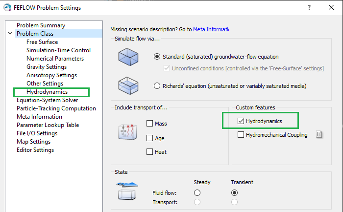
New Custom features "Hydrodynamics" in the FEFLOW Problem settings dialog.
Hydrodynamics - Coupling Settings
FEFLOW piMIKE1D supports both *.mhydro and *.m11 file formats to represent river model set-ups. In the future with the Linux support, the solution will support *.m1dx files.
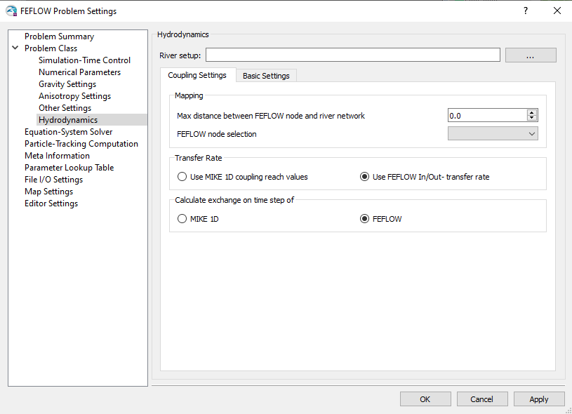
Hydrodynamics - Coupling Settings page in the FEFLOW Problem settings dialog.
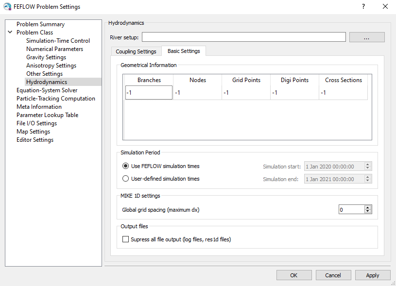
Hydrodynamics - Basic Settings page in the FEFLOW Problem settings dialog.
Mapping
The current coupling implementation carries out an automatic mapping between the FEFLOW nodes (associated to an existing Fluid-Transfer BC) and MIKE 1D H-grid points. The user requires to define a nodal selections through the Hydrodynamics - Coupling Settings page in the FEFLOW Problem Settings dialog. The selection contains a set of FEFLOW boundary nodes to be used for the coupling.
Each of the FEFLOW boundary node will be mapped to the closes H-grid point based on the Euclidian distance. The user can provide a Maximum distance between the FEFLOW node and the river network through the Coupling Settings page. For each FEFLOW boundary node, FEFLOW piMIKE1D searches for the closest H-grid point and store this connectivity for further use. If the H-grid points are non-equidistant, the resulting "snapping" distance could be distinct between upstream and downstream. During the model run a nodal distribution under the name "H-Point Mapping" is automatically created in FEFLOW. The user can review the resulting connectivity between the two meshes.
It is strongly recommended that the user verifies whether the current grid spacing in the surface water project is appropriate for the coupling with FEFLOW. The Grid spacing is controlled through the Computational control parameters from MIKE Hydro River GUI (see later below). Alternatively, FEFLOW user can simply adjust the Global grid spacing from Hydrodynamics - Coupling Settings page in the FEFLOW Problem Settings dialog.
In the case the FEFLOW river network should not be entirely used for the coupling, the user can work with a nodal selection in order to exclude the unnecessary Fluid-Transfer BC nodes. The mapping results are presented in a nodal distribution in FEFLOW. An example about the mapping between FEFLOW nodes and H-grid points is shown below.
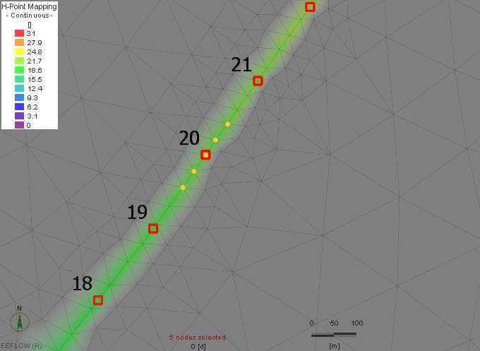
Example of the mapping between FEFLOW boundary nodes (current selection) and H-grid point (ID 20).
Transfer Rate
The exchange rate between the river and the aquifer is defined by the equation below, where PHI [m2/d] is the product of the exchange area [m2] and the leakage parameter [1/d]. The exchange area is the current wetted perimeter at the H-grid point multiplied with the sum of half the distances to the up- and downstream H-grid points. The wetted perimeter is based on the current water level and the cross-section geometry and is directly extracted on run-time from MIKE 1D.

The transfer rate (or leakage coefficient) is an user-defined parameter. The user can choose whether to use the FEFLOW In/Out-Transfer Rates values already available in the FEM document or extract the values from the river settings.
The leakage coefficient in the river settings is found in the section Boundary Conditions - MIKE SHE Couplings as shown in the Figure below and is a branch-dependent parameter.
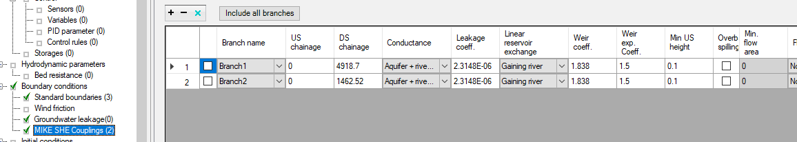
Definition of the leakage coefficient [1/s] in the surface water set-up in MIKE Hydro River GUI.
Calculation of exchange term
FEFLOW piMIKE1D is capable to accommodate either to the FEFLOW time steps or to the MIKE1D time steps. The decision is based on the option Calculate exchange on time step in the Hydrodynamics - Coupling Settings page in FEFLOW. Every numerical model is different in terms hydrodynamic behaviours on the surface water or groundwater processes, thus the user needs to evaluate what time resolution would be better suitable for capturing all the relevant physical processes.
Hydrodynamics - Basic Settings
Geometrical Information
In this section, an overview table of all extracted information from the river network is presented such as branches, nodes, cross-sections, etc. The information is read-only and automatically provided after the mapping between FEFLOW and MIKE1D is computed.
Simulation period
FEFLOW piMIKE 1D offers two possibilities to control the simulation period for the coupled calculation.
-
Option 1: The simulation starts at the MIKE 1D start date. The end date of MIKE 1D will be adjusted to match the FEFLOW simulation duration, calculated as the difference between FEFLOW's Final Simulation Time and Initial Simulation Time (in days).
-
Option 2: User-specified initial and final date-time in the new Hydrodynamics page in the FEFLOW Problem Settings dialog. The MIKE 1D start/end simulation will be adjusted to what is specified. The user should make sure the period is covered by required inputs for MIKE 1D, e.g. any time series for boundary conditions. The FEFLOW's Final Simulation Time will be adjusted accordingly.
MIKE 1D Settings
The discretizations level in the river network plays a significant role for the success of the coupling. piMIKE1D will always find a FEFLOW boundary node to be linked with a H-grid point. But if the amount of H-grid points is limited, the spatial changes of water level in FEFLOW may not be optimal reflected.
Through the Hydrodynamics - Basic settings page in the FEFLOW Problem Settings dialog, the user can control the Global grid spacing (maximum dx) in MIKE1D. The same parameter can be controlled from the MIKE11 or MIKE Hydro River GUIs.

Discretizations settings in MIKE 11 GUI.
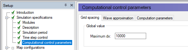
Discretizations settings in MIKE HYDRO River GUI.
Model results
The coupling solution utilizes the standard result formats in FEFLOW and MIKE Hydro River (or MIKE 11). If the option of FEFLOW Results *.dac file is activated before the model run, the user will be able to visualize the river changes through the values of Fluid Transfer BC.
|
|
In the case the Transfer Rates in FEFLOW are not used for the calculation of the exchange flows, instead the rates are computed on runtime and passed directly to the FEFLOW kernel, the on-the-fly budget calculation using the Rate Budget panel in the DAC file may not be correct. It is strongly recommend to create a nodal selection with the river nodes and activate the Budget-History Charting -> BCs before starting the simulation. This will assure that boundary budgets in the charts contain the real leakage coefficient. |

Apart from the standard MIKE1D log files, a <model>_Summary.html file will be created in the same directory as the river setup. The file contains some general information on the MIKE1D model and the water balance. For debugging purposes, the section “Couplings In-/Outflow mass error“ contains some hints about possible imbalances originated by the coupling.
The option Suppress all file output is intended in the case the same FEFLOW and MIKE1D projects are opened and executed at the same time, e.g. in the case of a scenario analysis. In order to avoid locking the results files from the MIKE1D side, the option can be used.
The log files created on runtime can be used for additional debugging purposes, other visualization and verification of the mapping between the FEFLOW nodes and the MIKE1D H-grid points. The files of available output files is shown below.
-
<model>_HPoint2NodeTable.txt: mapping between FEFLOW nodes and H-grid points (similar to ifm-m11 “IfmMIKE11_Patchfefnodes.txt”):
-
H-ID: unique id of the H-grid point. This can be used to match the H-grid point to the other log files.
-
Chainage: M-location of the H-grid point along the river branch.
-
H-X, H-Y, F-X, F-Y: coordinates (X,Y) of H-grid point and FEFLOW node, respectively.
-
Branch: Name of the branch the H-grid point belongs to
-
F-NODE: FEFLOW node number
-
Slice: slice number of the corresponding FEFLOW node
-
Branch: Name of the branch the H-grid point belongs to
-
-
<model>_HPoint2NodePoints.txt: One record for each FEFLOW node and each H-grid point that is part of the coupling. No column headers
-
0: json point-feature for the FEFLOW node/H-grid point
-
1: branch name
-
2: FEFLOW node number: empty for H-grid points
-
-
<model>_HPoint2NodeLines.txt: One record for each mapping between a FEFLOW node and an H-grid point. No column headers
-
0: json line-feature from node to H-grid point
-
1: branch name
-
2: H-grid point chainage
-
-
<model>_HPoints.txt: Information on H-grid points.
-
H-ID: unique id of the H-grid point. This can be used to match the H-grid point to the other log files
-
Chainage: M-location of the H-grid point along the river branch
-
X, Y: coordinates
-
Branch: Name of the branch the H-grid point belongs to
-