


The 2D Supermesh
A 2D Supermesh is the most basic geometrical definition to generate a finite-element mesh. The Supermesh consists in polygons, lines and points.
2D Supermesh Elements
Supermesh Polygons
A subdivision of the model area into a number of separate polygons can be useful for a number of reasons:
- Finite-element edges will honour the polygon boundaries, allowing for example an exact zoning of parameters and setting of boundary conditions at exact locations later.
- The required density of the finite-element mesh can be specified for each polygon.
- The polygons can be used for parameter assignment and results evaluation later.
Supermesh Lines
Lines in the Supermesh are applied to represent linear structures in the finite-element mesh to be created. Their advantages include:
- Finite-element edges will honour the line, providing for example the basis for later applying the boundary condition for a river exactly along the river axis.
- The mesh may be automatically refined during mesh generation along the line.
- The lines can be used for parameter assignment and results evaluation later.
Supermesh Points
Points in the Supermesh are typically placed at the locations of production or injection wells or at observation locations. They make sure that a finite-element node is set at exactly this location during mesh generation, they allow for local mesh refinement around the point, and they can be used for parameter assignment, e.g., to set the boundary condition for a pumping well.
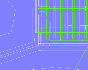
Example for a Supermesh detail.
Editing 2D Supermesh Features
Sets of polygons have to fulfil some requirements:
- No overlapping polygons are allowed.
- No polygons can be entirely contained by another polygon.
The user-interface tools ensure that these requirements are met at any time. Internal holes in the supermesh are possible. They are indicated by another color for the internal boundary as shown below:
Inner Supermesh border.
The  Mesh-Editor toolbar
provides the tools to digitize and edit Supermesh polygons,
lines, and points.
Mesh-Editor toolbar
provides the tools to digitize and edit Supermesh polygons,
lines, and points.
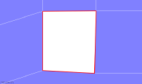
In Move Node mode, both the originally digitized nodes and smaller nodes in between can be moved. Moving the small nodes results in curved polygon edges (parabolic or circular shape) that are typically applied to curved structures such as borehole edges or pipe walls in small-scale models.
When digitizing a polygon next to an existing one, the editor will automatically follow the existing polygon boundary to close the new polygon.
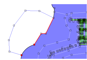
Follow existing boundaries.
Converting Map to Supermesh Features
Instead of digitizing Supermesh features
on screen, they can be imported from background maps. This conversion
can be done to a group of maps if the Supermesh
import from maps option is choose in the New
FEM Model dialog or to a single map file via the Convert
to Supermesh entry in the context menu on the name of the
map file in the  Maps panel.
All features of the map (or all selected features when applying an SQL selection query on the map) are converted to supermesh features using this approach. Polygons that would overlap with already existing polygons are not converted.
Further details of working with 2D Supermeshes are discussed in 2D Supermesh Design Workflow.
Export of Supermesh Features
Once a finite-element mesh has been generated,
all Supermesh features (points,
lines, polygons) are displayed in the
Maps panel. The export of
Supermesh features as maps
is available via the context menu of the Supermesh entry
or of the respective Supermesh features
in the Maps panel.