2D Supermesh Design
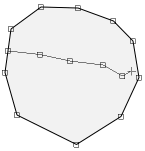
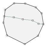
The Supermesh defines the framework for mesh generation. While in the simplest case the supermesh only consists in one single polygon defining the outer boundary of the model area, complex supermeshes can contain hundreds of polygons, lines, and points.
Each node of a supermesh, no matter whether in a polygon edge, a line, or as a single point, will be made a node of the finite-element mesh. Between the supermesh nodes, however, additional nodes may be inserted according to the current 2D Meshing settings during mesh generation.
The main reasons why to use more than a single polygon encompass:
- Force refinement in certain areas of the mesh.
- Consider linear or point structures, so that finite-element edges are aligned along the lines and mesh nodes are placed at the points.
- Force refinement along line or point structures.
- Use polygons/lines/points later on for parameter input.
Polygons, lines, and points can be digitized in
the Supermesh View, or they can be directly imported
from a map by using the New FEM Model
wizard or by using the context menu of the map in the  Maps
panel. When digitizing on screen, a snapping mode can be applied so that
all digitized points will be placed exactly on features of a selected
background map.
Maps
panel. When digitizing on screen, a snapping mode can be applied so that
all digitized points will be placed exactly on features of a selected
background map.
All functions to be used for supermesh design
can be found in the  Mesh-Editor toolbar and
  Mesh menu.
Polygon Design
Polygons can be digitized applying the Add Polygons tool in the Mesh-Editor toolbar or in the Mesh menu.
If snapping to features in background maps is
desired, the background map (s) to snap to have to be loaded in the Maps panel. The map to snap to is then selected
from the drop-down list in the Mesh-Editor toolbar. Snapping can either be
done to points (nodes of polygons or line features in the map) or lines
(projection onto the edges of polygons or lines). Direct coordinate input
is possible by pressing <F2> on the
keyboard, opening the Pin Coordinates toolbar.
For drawing more than one polygon, additional
polygons can be started independently, by clicking on an existing node
(highlighted in red), or by clicking on an existing edge, hereby inserting
an additional node. Also while digitizing, new nodes can be added to existing
edges just by clicking on an edge.
 |
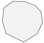
Each polygon is closed by clicking on the first node again. In case of neighboring polygons, FEFLOW automatically closes the polygon along existing polygon edges in a way that no overlapping occurs. The corresponding polygon border is shown in red when placing the mouse onto the first node of the polygon without clicking. |
Overlapping polygons are not allowed, and if a newly drawn polygon would cause overlaps, the polygon cannot be closed and a warning message is shown.
Returning to and clicking on an already existing node of the currently digitized polygon removes all nodes set in between.
 |
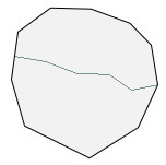
Finished polygons are shaded in grey. The outer border of the modeling area is drawn as a thicker black line, while inner borders (around gaps) are shown in brown (default colors). This can be used as a check for unintended gaps in the supermesh. |
Line and Point Design
Lines and points can be digitized applying the Add Lines or Add Points tools in the Mesh-Editor toolbar or in the Mesh menu.
If snapping to features in background maps is desired, the background map (s) to snap to have to be loaded in the Maps panel. The map to snap to is then selected from the drop-down list in the Mesh Editor toolbar. Snapping can be either done to points (nodes of polygon or line features in the map) or lines (projection onto the edges of polygons or lines). Direct coordinate input is possible by pressing <F2> on the keyboard, opening the Pin Coordinates toolbar.
Correction and Editing
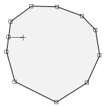
Nodal corrections, such as moving single nodes, adding nodes, and creating curved polygon edges can be done using the Move Node tool.
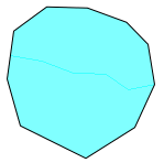
Polygons can be split using Split Polygon in the Mesh-Editor toolbar or in the Mesh menu. Splitting always starts and ends at a polygon edge. At the starting point and end point an additional node is inserted if splitting is not started/ended at an existing node.
|
Snapping to background maps is also possible when splitting polygons. |
A number of polygons can be merged by selecting the corresponding polygons (using one of the selection tools in the Mesh-Editor toolbar or in the Mesh menu) and clicking the Join Polygons tool.