


Workflow 1: Material Regions from scratch
Parameter lookup tables allow the definition of named properties, e.g., material types, each representing a set of parameters, such as conductivity, drain- /fillable porosity, etc. When assigning a parameter, the property name can then be used instead of assigning a value.
By using this parameter table, the user could include all the conceptual selections (e.g., geological units), and assign their corresponding parameters efficiently. This way, the user can dedicate more time to the conceptual model and less to meshing. Material regions allow an easier update of existing models (e.g., re-meshing, re-assignment of parameters).
A demo file for this tutorial can be found under the demo folder when you install FEFLOW and the accompanying DEMO package.
(by default: C:\Users\Public\Documents\DHI FEFLOW 7.5\demo)
This Workflow 1 shows you how to prepare the Parameter Lookup Table from scratch, and how to manually prescribe the material regions to each supermesh polygons:
-
Step 1 : Preparation of Dataset in Parameter Lookup Table
-
Step 2 : Assignment in Supermesh
-
Step 3 : Assignment in FEM file
 |
As soon as a finite-element mesh has
been generated, FEFLOW considers a 2D horizontal problem under
confined conditions by default. Since the To add one specific parameter, you have to first set a related problem class. Therefore, it is recommended to create different lookup tables in a stepwise manner from lower problem classes (2D) to complex problem classes (3D/Mass/Heat Transport) in order to progressively unlock the required parameters. Note that 3D Parameter like Kxx, Kyy, Kzz, In/outflow on top/bottom is unlocked afterwards when you expand the 2D model to 3D. Note that parameters Kxx, Kyy, Kzz, In/outflow on top/bottom will be inherited from the 2D model: Conductivity [max] and Transmissivity will be used in unconfined and confined models, respectively; Sink/Source term will be assigned to In/outflow on top/bottom. The database Lookup Table can also be later exported/imported to other models. |

Step 1: Preparation of Dataset in Parameter Lookup Table.
1) In FEFLOW, the user is allowed to define the Problem Class even in an empty new project. Please click on New to create an empty model.
Create New Project.
2) Go to Problem Settings > Problem Class to specify the class of your conceptual 2D model. An example is shown below:
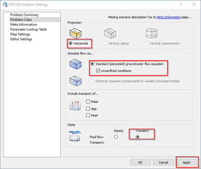
Define Problem Class.
3) Within the same window, switch to the section called Parameter Lookup Table, click on the Green Plus to Add a new lookup material:
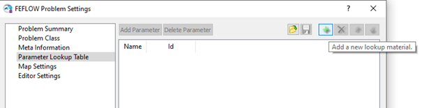
Add a new Lookup material.
4) Assign the name to the first material by double-click on the available blank space, e.g. Gravel:
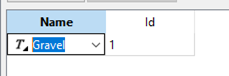
Name a new material.
5) Click on Add Parameter:
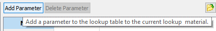
Add Parameter.
6) Now you can add relevant Material Properties to each material:
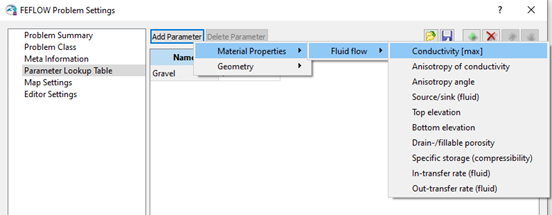
Add Material Properties.
7) After that, it is possible to prescribe the values of each parameter:
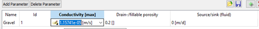
Prescribe Parameters.
The Units can be changed by right-clicking on the corresponding space:
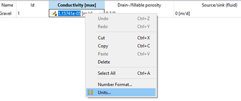
Change Units.
8) Similarly, more conceptual material objects can be created:
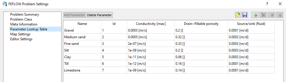
Overview of Lookup table example.
9) Import/export option of the table is supported. You can modify the XML file directly in your favorite text editor (e.g., Notepad++) afterwards.
For more details of Parameter Lookup Table, please refer to this link.
|
Please note that Parameter Lookup Table currently only supports the XML format.
|
Step 2: Assignment in Supermesh
In FEFLOW, the user can save the Problem Class and Parameter Lookup Table directly at the Supermesh level (XML format).
As soon as the lookup table of material regions is created, the different materials can be assigned directly to the polygons in the supermesh.
As shown below, the material region Gravel is assigned to Polygon 6. After selecting Gravel, please do not forget to press <ENTER> key to confirm the definition.
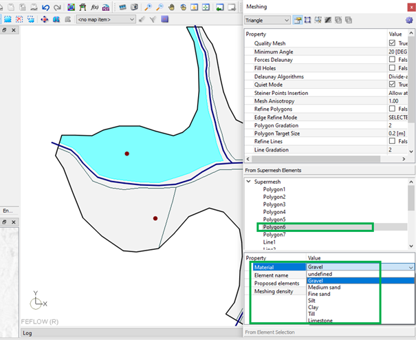
Define Material for Polygon.
When the text becomes bold, the definition is assigned:
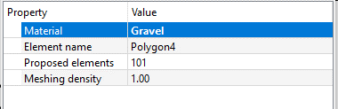
Press ENTER key to confirm the definition.
Note that each supermesh polygon can only be assigned one material.
Only when you save the supermesh as XML Supermesh format, the definitions for Materials will also be saved.
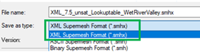
Save supermesh as XML type format.
Please note that due to inheritance relationships, operations on supermesh polygons (such as merging or splitting) may change the material regions previously defined in the polygons. It is recommended to double check the correct assignment when performing such operations.
Step 3: Assignment in FEM file
The assignment of the lookup table is successful if the Problem Class matches the lookup table parameters. If the parameter doesn’t exist in one specific Problem Class, the automatic assignment will not happen. (e.g. the defined parameter Conductivity [max] in lookup table doesn’t exist in the horizontal 2D saturated model, instead, there is another similar parameter called Transmissivity [max]).
Under Data Panel – Material Properties, there is a new distribution called Material regions that matches the material assignment from supermesh. All related parameters, such as Conductivity [Max], Source/Sink, Drain-/fillable porosity were automatically assigned while meshing.
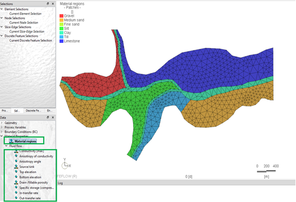
Material regions.
Unlike previous older FEFLOW versions (<7.5), all material properties are not lost when the user regenerates the mesh; they are automatically saved and re-assigned:
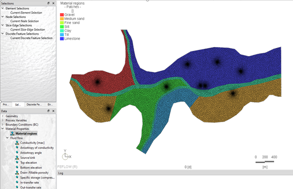
Mesh regenerated by the Triangle method, the parameters are still retained.
The Material Regions can be changed after the mesh generation: you need first an element selection, and assign this area using the combo-box with the list of all material names. This operation is analogue to the assignment of Inactive/elements.
Furthermore, all parameters, e.g. Conductivity [Max], can be also locally changed.
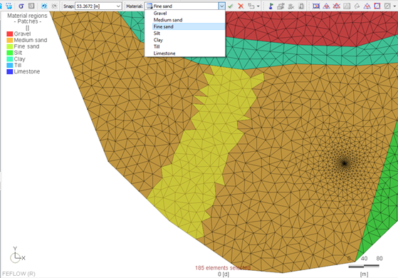
Assignment of Material regions after mesh generation.
When you go to a parameter, e.g. Conductivity [Max], select all elements and click on Reset to Default. The Conductivity [Max] will change back to the default value or to the corresponding specified value in the Parameter Lookup Table.
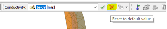
Reset to default value.
Material Regions of 3D Layer-based Model and 3D Unstructured Mesh
The 2D model above can be extended to a layer-based 3D model. It is recommended to double check whether the parameters are correctly assigned during this operation.
After extending to a 3D layer-based model, the Material Region definition will first exist only for Layer 1, however, the corresponding parameters such as Kxx, Kyy, Kzz have been automatically inherited from the 2D model and in the vertical direction all layers have defaulted to the same K-value. But, of course, the Material Region in 3D model can be also manually modified as user required to beter match with geology model.
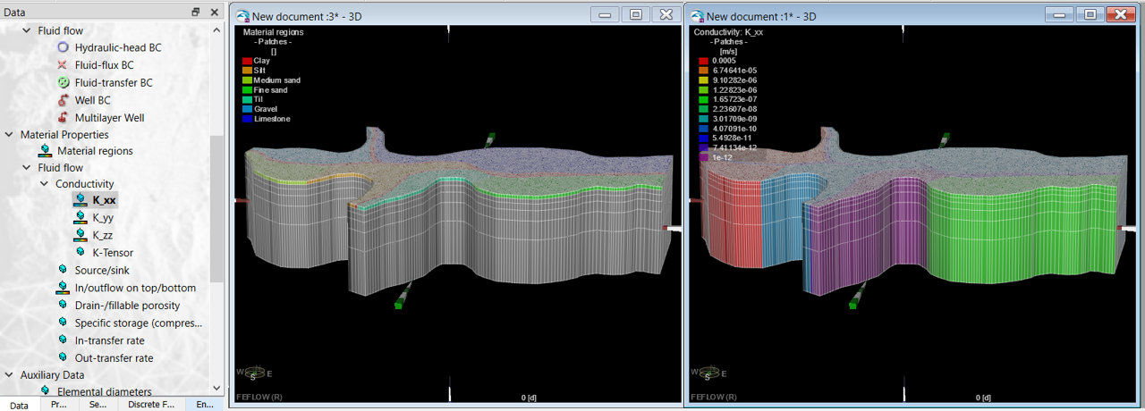
3D Layer-based Model.
|
|
Be aware that also In/outflow on top/bottom will be assigned on the top and on the bottom layers of the model. The user should delete manually the values from the bottom layer, to avoid undesired inflow of water. |
TetGen mesh generator can further converts 3D layer-based models into unstructured meshes. Please pay attention to the choice of interpolation methods in TetGen, because the material regions also need to be interpolated. Under certain circumstances, improper element interpolation methods may lead to some material regions not being assigned to certain tetrahedrons. Please refer to Inheritance of Model Data of TetGen mesh generator.