


Fluid-Flow Boundary Conditions - Overview
By default, all model boundaries in FEFLOW are assumed to be impermeable, i.e., no water can flow into the model or out of the model. At boundaries where this is not true, boundary conditions have to be set specifically. Boundary conditions can be placed both at outer model borders and inside the model.
Boundary conditions are defined on a nodal basis. However, some of them (Fluid-flux BC and Fluid-transfer BC) have to be applied to more than one node to be fully functional.
The following four basic types of boundary conditions are available in FEFLOW. All of them can be used as time-constant or in combination with a time series. The application of all the boundary conditions can be constrained by additional physical constraints.
| Symbol | Boundary Condition | Short Description | Examples |
|---|---|---|---|
 |
Hydraulic-head BC | Fixed hydraulic head (1st kind/Dirichlet boundary condition). |
|
 |
Fluid-flux BC | Fixed flux (Darcy flux) across a model boundary (2nd kind/Neumann boundary condition). |
|
 |
Fluid-transfer BC | Fixed reference water level with additional transfer rate (3rd kind/Cauchy boundary condition) |
|
 |
Well BC | Fixed abstraction/infiltration at a single node or along a well screen. |
|
 |
Multi-layer wells | Fixed abstraction/infiltration along a well screen. |
|
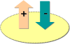 |
For defining boundary conditions, inflows are considered as negative, outflows as positive. |
|
|
FEFLOW only allows one type of boundary condition to be set at a node. Inputting another type of boundary condition will erase the previously defined condition. |

A number of more specific boundary condition types
can be added additionally via the context menu of the Fluid
Flow section in the Boundary Conditions
(BC) branch of the  Data
panel. These are by default hidden.
Data
panel. These are by default hidden.
| Symbol | Boundary Condition | Short Description |
|---|---|---|
|
Hydraulic-head BC (Pressure) | Input and visualization of hydraulic-head BC via pressure values |
|
Hydraulic-head BC (Saltwater Head) | Input and visualization of hydraulic-head BC via saltwater head values (otherwise equivalent freshwater head) |
|
Hydraulic-head BC (Saturation) | Input and visualization of hydraulic-head BC via saturation values |
|
Hydraulic-head BC (Moisture content) | Input and visualization of hydraulic-head BC via moisture content values |
 |
Fluid-flux BC (Gradient) | Gradient-type fluid-flux boundary condition for unsaturated models |
 |
Fluid-flux BC (Integral) | Integral fluid-flux boundary condition for unconfined models with free & movable surface |
 |
Fluid-transfer BC (Integral) | Integral fluid-transfer boundary condition for unconfined models with free & movable surface |
|
|
When using the alternative options for hydraulic-head BC, all values are only converted to/from hydraulic head at input or when visualizing. Internally, only hydraulic head values are stored. Thus nodal elevation values (for pressure and saltwater head), density ratio (for saltwater head), or unsaturated material properties (for saturation/moisture content) have to be set correctly to allow a correct conversion. |
Constraints on Fluid-Flow Boundary Conditions - Overview
The application of boundary conditions in FEFLOW can be constrained by physical limits. The combination of boundary conditions and time-constant or time-varying constraints allows the representation of a broad variety of specific boundary properties. Examples include seepage faces, pumps with a minimum water level, and temporal rivers.
Most constraint conditions are complementary constraints, i.e. boundary conditions of a head type (hydraulic head, fluid transfer) can be constrained by a minimum and maximum flow rate, boundary conditions of a flux type (fluid flux, well) can be constrained by a minimum and maximum hydraulic head. For fluid-transfer boundary conditions, an additional hydraulic-head constraint is available.
A seepage face can serve as an example:
 |
In the model, for the entire air side of a dam (cross-sectional model in this example) a fixed head boundary condition is set, with the head value equal to the elevation of each node. The boundary conditions are constrained by a maximum flux = 0 m³/d, which means that the head boundary condition is only active in case of water flowing out. |
 |
At any time during the simulation, head conditions above the water level would start infiltrating because the fixed head (set equal to elevation) is higher than the hydraulic head at the surrounding nodes. However, the constraint condition inhibits inflow. At nodes where the constraint is activated (above the water table), the head boundary condition is automatically converted into a well boundary condition with the value of the constraint (0 m³/d in this example). |
So technically, boundary condition constraints (BCC) are implemented in FEFLOW by converting the type of boundary condition when the constraint is activated. This can be used to check where the constraint condition was fulfilled.
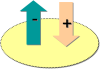 |
For defining constraint conditions, inflows are considered as positive, outflows as negative. Thus a constraint of maximum flow rate = 0 m³/d means that no inflow is allowed at the corresponding boundary condition. |