


FEFLOW Parameters
Introduction
The task of assigning model parameters is in many cases repeatedly performed during model setup and application. After the initial parameterization, model properties may have to be changed during calibration, or parameters need to reflect different scenarios. Thus, the workflows for parameter assignment are crucial for the efficient handling of a groundwater model.
Typical assignment procedures are based on the activation of a property to be assigned and the selection of the target nodes or elements. The tools for selecting nodes or elements are described in detail in chapter.
There are some exceptions from this standard workflow: When working with map data, FEFLOW provides the means to automatically activate a parameter and/or select the target geometry based on information in the map or linked to the map.
Input Parameters
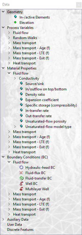
FEFLOW distinguishes between seven groups of parameters,
all of them visible on the first level of the tree view in the  Data panel:
-
Geometry
-
Process Variables
-
Boundary Conditions
-
Material Properties
-
Auxiliary Data
-
User Data
-
Discrete Features
Data panel.
Geometry
The geometry section of the
Data panel contains the option
to set mesh elements active or inactive for a simulation and the node
elevation values in 3D models. With
the elemental parameter In-/active
Elements mesh elements
can be activated or deactivated during the entire simulation or only at
specific time stages. By default, all mesh elements are active after mesh
generation.
In 3D models, Elevation is included in the geometry section as a nodal parameter. In models with a fixed mesh, the elevation does not change during the simulation. In models representing a phreatic surface with the free approach, the actual nodal elevation changes during the course of the simulation. The parameter Reference Elevation preserves the original node elevations.
Process Variables
Process variables include the primary variables hydraulic head, mass concentration, mean age, mean lifetime expectancy, exit probability and temperature (as applicable). When setting up the model, they describe the initial conditions. During and after the simulation these process variables reflect the then-current conditions.
Other process variables contain values derived from the original primary variables. For example, pressure is not stored separately in FEFLOW, but calculated from hydraulic head and elevation ‘on the fly’. When these secondary parameters are used as input variables, the input is converted into the original primary variable based on current conditions.
The third type of process variables are auxiliary variables supporting results evaluation and visualization, such as Darcy flux, rate and period budget and streamlines or pathlines. They cannot be used as input parameters.
Boundary Conditions
Boundary conditions are defined on the mesh nodes similar to the process variables. Each problem class in FEFLOW has its own set of boundary conditions, which are used to solve the system of equations defined in the finite-element problem. Moreover, boundaries can have auxiliary parameters such as Boundary Condition Constraints and Modulation Function.
All information you need to know about this type of parameter is described in detail in the section Boundary Conditions.
Material Properties
The material properties describe the relevant characteristics of the porous medium for the considered flow and transport processes to be simulated. They are defined on an elemental basis.
For the flow simulation, material properties encompass quantities such as hydraulic conductivity in different directions according to the selected anisotropy model, drain-/fillable porosity (specific yield) and specific storage (compressibility), and transfer rates (e.g., to represent river-bed conductance). Parameters such as source/sink or in/outflow on top/bottom (often used for groundwater recharge) are mathematically close to boundary conditions; however, their typically distributed spatial reference justifies their placement in material properties.
Auxiliary Data
Auxiliary data cannot be edited or assigned but can be used to check some properties of the finite-element mesh. They are classified on physically-based and geometrically-based auxiliary data. More details are discussed in section Auxiliary Data.
User Data
User data are additional nodal or elemental distributions that can also be based on user-defined expressions. Assignment and usage are discussed in section User Data.
Discrete Features
Discrete features can be added along element edges or faces to represent high-conductivity features or they can connect two arbitrary nodes. In FEFLOW 8.0 the concept of Dual Node Connectors have been introduced to allow a virtual separation between the standard finite elements and the discrete feature elements. This can be used for applications with low permeable discrete features.