


Boundary Conditions
While the differential equations for groundwater flow and transport describe flow and transport within the model area, also conditions for the boundaries of the simulation region have to be defined. The default boundary condition in FEFLOW is no flow, i.e., no water/solute/heat flow is possible across the boundary. If any other condition is desired, a boundary condition has to be set to the corresponding node (s).
The boundary conditions are described more in detail in the sections:
The application of all kinds of boundary conditions can be constrained by physical limits (constraints). Further information is described in the section Boundary Conditions Constraints.
Boundary condition values can be modulated and the conditions themselves can be turned on and off by the application of Modulation Functions.
|
|
Groundwater recharge and volumetric sources/sinks are found in Material Properties as they are typically applied to an area or volume, while boundary conditions are set on a nodal basis. |

Depending on their mathematical definition, the FEFLOW boundary conditions can be also classified as follows:
| Dirichlet type | Neumann type | Cauchy type | Nodal source/sink type | Special boundaries (3D only) |
|---|---|---|---|---|
| Hydraulic-head BC | Fluid-flux BC | Fluid-transfer BC | Well BC | Multilayer Well (flow) |
| Mass-concentration BC | Fluid-flux BC (Gradient) | Mass-transfer BC | Mass nodal sink/source BC | Borehole Heat Exchanger (heat) |
| Age-concentration BC | Mass-flux BC | Heat-transfer BC | Heat nodal sink/source BC | |
| LTE-concentration BC | Heat-flux BC | |||
| Probability BC | ||||
| Temperature BC |
For groundwater age, only the first boundary condition
type is displayed by default and additional types have to be added via
the respective context menu in the  Data panel. Except for Borehole Heat Exchangers, the sign
convention for boundary conditions in FEFLOW defines flows out of the
model as positive (e.g., well abstraction), while inflows are negative.
Notably, this convention differs from other parts of FEFLOW, such as the
Rate-Budget and Period-Budget
or the Subdomain Boundary Rate Budget
and Subdomain Boundary Period Budget panels
or the definition of constraints, where inflows are considered as positive,
outflows as negative.
Data panel. Except for Borehole Heat Exchangers, the sign
convention for boundary conditions in FEFLOW defines flows out of the
model as positive (e.g., well abstraction), while inflows are negative.
Notably, this convention differs from other parts of FEFLOW, such as the
Rate-Budget and Period-Budget
or the Subdomain Boundary Rate Budget
and Subdomain Boundary Period Budget panels
or the definition of constraints, where inflows are considered as positive,
outflows as negative.
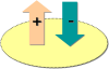
Algebraic signs for boundary conditions.
Dirichlet-type BCs
This boundary condition type - often also referred to as 1st kind boundary condition - specifies a time-constant or time-varying value for the primary variable at a node, i.e. hydraulic head for flow, concentration for mass transport, groundwater age and lifetime expectancy, probability of exit and temperature for heat transport. The inflow or outflow to/from the model domain at the node can be calculated from the simulation result.
In certain model types, such as unsaturated or density-dependent simulations, it is possible to derive the boundary-condition value from input such as:
-
Pressure
-
Saltwater Head
-
Saturation
-
Moisture Content
While converting input from a different quantity in these cases, and providing the possibility to visualize the boundary conditions in terms of another quantity, the actual boundary condition stored and used during the simulation is always a Hydraulic-head BC.
Neumann-type BCs
The flux-type boundary condition describes an in- or outflow of water/mass/energy at element edges (2D) or element faces (3D). Though nodally defined, the condition must be applied for at least two adjacent nodes (2D) or all nodes of a vertical or horizontal element face (3D) to be effective. The given value in flow simulations is a Darcy flux perpendicular to the boundary. An optional alternative formulation for unsaturated models allows the definition of a hydraulic-head gradient instead of the Darcy flux.
The successful application of Mass-flux BCs and Heat-flux BCs is linked to the application of the convective or divergence form of the transport equation.
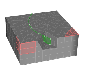
Flux and transfer boundary conditions in 3D model.
Cauchy-type BC
Fluid-transfer BCs can be used to describe rivers, lakes, and known hydraulic heads in a distance from the model boundary (sometimes called "general head" boundaries). The condition is used to apply transfer properties between a reference value for the primary variable (hydraulic head, concentration, or temperature) and groundwater. Thus the value of the boundary condition is a reference hydraulic head (e.g., river water level), reference concentration, or reference temperature. The hydraulic conductance (e.g., properties of a clogging layer), mass-transport conductance or thermal conductance are defined as material properties on elements adjacent to the boundary condition. Similar to the Neumann-type BC the transfer boundary condition must be specified along a line (2D) or for an entire element face.
Nodal source/sink-type BCs
Well BCs and their counterparts for mass and heat transport simulation are nodally applied and represent a time-constant or time-varying local injection or abstraction of water, mass or energy at a single node or at a group of nodes.
If it is intended to simulate a well screened in different layers it is recommended to use the Multilayer-Well BC.
The successful application of Mass nodal sink/source BC and Heat nodal sink/source BC is linked to the application of the convective or divergence form of the transport equation.
|
|
The resulting hydraulic head at well nodes depends on the local spatial discretization. Quantitative comparisons should be made with care. |
